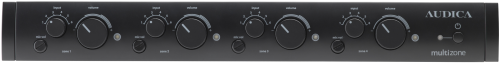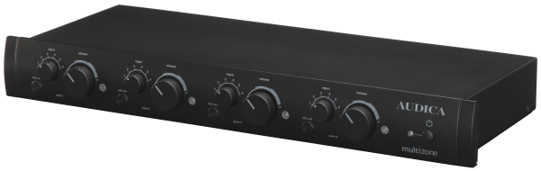

MULTIzone description:
A zone control mixer consisting of 4 zones with 6 music inputs plus a microphone input for paging applications. Each of the 4 outputs can be independently configured to provide music from any one of the inputs plus the paging microphone and the relative levels are set by front panel controls. The music is automatically reduced in level (ducking) to allow for announcements to be heard clearly. Each zone output is mono and all inputs are stereo capable (mixed to mono internally).
Zone outputs can have flat response or Audica loudspeaker EQ, as required. A mute
control input is provided to be linked to fire control systems. This mutes all music
inputs whilst keeping the paging microphone active for safety announcements. Remote
zone control is possible via wired control panels or an RS232 interface. Up to 7
MULTIzone units can be linked (daisy-
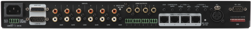
Inputs:
Stereo Phono jack pair for input 1, 2, 3, 4, 5, 6
XLR balanced input for paging microphone. (48V Phantom power option provided)
15-
There are also five control inputs: Remote zone control on RJ45 connector for zone 1, 2, 3, 4 and RS232
Other:
AC supply on IEC 3-
MUTE input for fire control panel on Phoenix connectors. This can be wired for isolated
contacts (Normally Open) or a voltage input (3-
Outputs:
Eight outputs are available and a loop-
Mono phono jack output for zone 1, 2, 3, 4. Selectable flat or AEQ curve.
Balanced audio output on Phoenix connector for zone 1, 2, 3, 4. Replicates phono jack output for zone.
15-
Controls:
Front panel:
Mains power switch (full AC line switch -
zone 1, 2, 3, 4 source selector. zone 1, 2, 3, 4 music level control.
zone 1, 2, 3, 4 page mic mixing level. (When set to zero music ducking is disabled for that channel)
Rear panel:
Rotary potentiometer to set gain for input 1, 2, 3, 4, 5, 6. Rotary potentiometer to set gain of Microphone input.
DIP switch to enable 48V phantom power for Microphone input.
Rotary potentiometer to set compressor contribution to mic channel.
Rotary potentiometer for low-
Rotary potentiometer for mid-
Rotary potentiometer for music ducking "floor level" (music attenuation level).
Rotary potentiometer for music ducking release time (music fade-
DIP switch to set the MIC source (input or loop-
Three DIP switches for RS232 address setting (1 to 8).
DIP switch for RS232 source switch (input or loop-
Four DIP switches to enable Audica speaker EQ (AEQ) on each output channel.
Front panel Indicators:
Power LED. Off when Mains power switch is off. Blue when mains power is on. Short-
Channel indicators. Each channel has a white indicator LED to show signal present. The brightness of the LED gives some indication of signal level.
Rear panel Indicators:
MIC LED. This is a 2-
Input channels. A single 2-
RS-
The RS-
Functional description:
Each of the 4 zones has independent controls for all variables. A rotary switch selects which input is used for that zone and the level of the music is set by a rotary control, both on the front panel. The mix of the microphone into the zone is controlled by a separate "preset" style rotary control, adjustable via a screwdriver on the front panel. When the microphone signal exceeds a threshold the music level is reduced automatically to a level which allows the microphone signal to be clearly heard (This attenuation is adjustable on the rear panel).
Each zone has both single-
Maximum output level on Line output jacks is 4.0Vrms
Maximum output level on Balanced output jacks is 8.0Vrms, electronically balanced.
If taking a single-
Each input has independent gain control to allow matching of source levels, preventing
level jumps when selecting a different music sources and optimising the signal to
noise ratio of the system. The microphone input also has a gain control to match
a variety of microphones to the required optimum input level. Since the gain range
on the Mic input is +50dB to -
The input voltage range for Line in is 240mV (Maximum gain) -
The input voltage range for Mic in is 4.00mV (maximum gain) -
A pair of tone controls is provided for the microphone input to help compensate for any weaknesses in the microphone response. A variable compressor effect is also provided to help level out differences in loudness caused by different microphone users. This also helps prevent overload of the loudspeakers from any knock or pop noises received by the microphone or the differing mic technique of various users. 48V phantom power is available for active or condenser type microphones.
Some buildings require that the music system is muted if the fire alarm is triggered.
Two types of input are provided on the unit for this purpose. A set of isolated contacts
can be wired in (e.g. a relay activated by the fire control panel) or a voltage input
can be accepted (3-
The RS232 control port allows all the main user interface features to be controlled from a PC/Crestron/AMX etc. Output channels can be independently switched to RS232 control whilst leaving others working from their front panel controls or remote keypads; this gives great flexibility in system configuration.
The RS232 input has additional functionality in that it can be used to put the unit in standby. A specific "Standby" command will reduce power consumption to <0.5W by shutting down all internal systems. An "Operate" command can then restore system operation but it is important to note that the unit will take several seconds to fully awake, during which time no audio will be heard and no other RS232 commands can be received or acted upon. The programming of the RS232 controller device must take this into consideration.